
Background#
The radio included with my VZ Calais is not a bad one by any stretch. It has many of the standard functions of a decent in dash car stereo; AM/FM Tuner, 6 Stacker CD player, phone kit compatibility, 5 preset EQ settings, and treble and bass controls. It even has some fancy functionality of speed dependent volume and distortion limiting. Unfortunately for me, it has one glaring omission: an auxiliary input. That prompted me to find or develop a solution.
Research#
I’ve seen several posts about how to achieve input on these units, either by de-soldering output capacitors and switching using a relay, or even as simple as soldering an input cable in parallel with the input of the amplifier and subsequently playing a ‘blank’ (or silent) CD when using the input. These options are okay, but neither are great; using a relay requires an external switch and it can interfere with the function of the phone input, this drawback is one that I didn’t want to deal with. I also didn’t want to load a CD of silence into my stacker.
After searching for a while, I stumbled across this post: http://www.carmodder.com/viewtopic.php?f=254&t=19628 by Nemesis04 at carmodder.com. Unfortunately, the site had changed servers since the original post and the attachments and images were lost in the transition. Fortunately for me, key information that I needed was there: the TDA7348 chip has an available input and the chip is controlled by I2C. A quick internet search revealed the datasheet for the TDA7348 and I was easily able to identify the I2C bus pins. Looking at the radio circuit board revealed that the input not in use, Input 1, has solder pads available for connection. Just a note for those of you attempting this mod; the inputs must be capacitor coupled and 1uF is recommended by the data sheet.
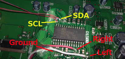
I2C bus and audio input connections
Testing#
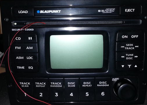
As I don’t have the security code for my radio, the easiest choice was to do all my testing in the car. In order to test withe cover on, I had to create an accessible connection for the I2C bus. I used 30AWG wire wrapping wire, also known as kynar wire, and brought the connection out through the CD slot. This worked surprisingly well and I was still able to use the slot, which I found out when I accidentally ejected the CD while the unit was reinstalled in the car. To my surprise, the wire did not interfere.
To sniff the I2C bus, I used my Bus Pirate (http://dangerousprototypes.com/docs/Bus_Pirate) I logged the commands sent when changing the inputs:
To FM:
[0x88+0x08+0x81+]
[0x88+0x14+0x1F+0x1F+0x1F+0x1F+]
[0x84+0x00+0x00+0x00+0x00+0x00+0x00+]
[0x88+0x03+0xFF+]
[0xC2+0x20+0x4F+0xAA+0xA8+0x60+0x64+]
[0xC2+0x20+0x4F+0x2A+]
[0x88+0x02+0xF8+]
[0x88+0x01+0x10+]
[0x88+0x00+0x35+]
[0x88+0x14+0x00+0x00+0x00+0x00+]
[0x88+0x08+0x80+]
[0x88+0x02+0xF4+]
[0x88+0x01+0x10+]
[0x88+0x02+0xF0+]
[0x88+0x01+0x10+]
[0x88+0x02+0xEC+]
[0x88+0x01+0x10+]
[0x88+0x02+0xE8+]
[0x88+0x01+0x10+]
[0x88+0x02+0xE4+]
[0x88+0x01+0x10+]
[0x88+0x02+0xE0+]
[0x88+0x01+0x10+]
[0x88+0x02+0xDC+]
[0x88+0x01+0x10+]
[0x88+0x02+0xD8+]
[0x88+0x01+0x10+]
[0x88+0x02+0xD4+]
[0x88+0x01+0x10+]
[0x88+0x02+0xD0+]
[0x88+0x01+0x10+]
[0x88+0x02+0xCC+]
[0x88+0x01+0x10+]
To CD:
[0x88+0x08+0x81+]
[0x88+0x14+0x1F+0x1F+0x1F+0x1F+]
[0xC2+0x20+0x4F+0xAA+0xA8+0x60+0x64+]
[0xC2+0x20+0x4F+0x2A+]
[0x84+0x00+0x00+0x00+0x00+0x00+0x00+]
[0x88+0x03+0xDD+]
[0x88+0x02+0xF8+]
[0x88+0x01+0x10+]
[0x88+0x00+0x39+]
[0x88+0x14+0x00+0x00+0x00+0x00+]
[0x88+0x08+0x80+]
[0x88+0x02+0xF4+]
[0x88+0x01+0x10+]
[0x88+0x02+0xF0+]
[0x88+0x01+0x10+]
[0x88+0x02+0xEC+]
[0x88+0x01+0x10+]
[0x88+0x02+0xE8+]
[0x88+0x01+0x10+]
[0x88+0x02+0xE4+]
[0x88+0x01+0x10+]
[0x88+0x02+0xE0+]
[0x88+0x01+0x10+]
[0x88+0x02+0xDC+]
[0x88+0x01+0x10+]
[0x88+0x02+0xD8+]
[0x88+0x01+0x10+]
[0x88+0x02+0xD4+]
[0x88+0x01+0x10+]
[0x88+0x02+0xD0+]
[0x88+0x01+0x10+]
[0x88+0x02+0xCC+]
[0x88+0x01+0x10+]
In the above code, [ is a start, ] is a stop and + is an ACK.
And from these I was able to create a command sequence (show in Bus Pirate compatible format) to switch to the other input on the TDA7348 chip:
1.  [0x88,0x08,0x81]
2.  [0x88,0x14,0x1F,0x1F,0x1F,0x1F]
3.  [0x84,0x00,0x00,0x00,0x00,0x00,0x00]
4.  [0x88,0x03,0xDD]
5.  [0x88,0x02,0xF8]
6.  [0x88,0x01,0x10]
7.  [0x88,0x00,0x32]
8.  [0x88,0x14,0x00,0x00,0x00,0x00]
9.  [0x88,0x08,0x80]
10. [0x88,0x02,0xF4]
11. [0x88,0x01,0x10]
12. [0x88,0x02,0xF0]
13. [0x88,0x01,0x10]
14. [0x88,0x02,0xEC]
15. [0x88,0x01,0x10]
16. [0x88,0x02,0xE8]
17. [0x88,0x01,0x10]
18. [0x88,0x02,0xE4]
19. [0x88,0x01,0x10]
20. [0x88,0x02,0xE0]
21. [0x88,0x01,0x10]
22. [0x88,0x02,0xDC]
23. [0x88,0x01,0x10]
24. [0x88,0x02,0xD8]
25. [0x88,0x01,0x10]
26. [0x88,0x02,0xD4]
27. [0x88,0x01,0x10]
28. [0x88,0x02,0xD0]
29. [0x88,0x01,0x10]
30. [0x88,0x02,0xCC]
31. [0x88,0x01,0x10]
In the above commands, first the chip is muted then the speakers are muted (Lines 1 and 2), then the EQ is set to off (Line 3), the bass and treble is set (Line 4), the volume is set low (Lines 5 and 6) the input is set to input 1(the originally unused input) (Line 7), the mute and speaker mutes are turned off(Line 8 and 9) and the volume is ramped back up (Lines 10+).
Implementation#
So where to from here? Well, I created a temporary solution using the above commands, sent via a PIC18, however I’ve run across several frustrating behaviours of the unit. Firstly, it switches the input when changing EQ settings, pausing the CD mutes the output and also changes the input on play. Also the above commands were captured with the unit at very low volume, meaning I have to turn up the volume after each switch. I have a few ideas on how to fix these issues and I’ll keep you posted.
Update I interfaced with the radio’s buttons by listening to the SPI bus connected between the faceplate and the main board.
Update 2 I’ve put the code I developed for the Microchip PIC24F Microstick on my GitHub
Update 3 I sold the car, so I no longer have access to the radio.
If you’re interested in this project, you can always contact me